Introduction
In Previous blog, we covered Static routing on NSX-T Tier-0 router with Active-Active mode. In this blog, we will cover OSPF configuration on NSX-T Tier-0 router to achieve North-South connectivity.
Topology Overview
Refer below topology diagram to get high level overview of infrastructure.

Figure 1: Topology Overview
We have Admin PC (172.20.10.80) which is connected to Physical Router andwill be considered as underlay Infrastructure. NSX-T Datacenter have Tier-0 router deployed in Active-Active mode. We have NSX-T edge cluster which are hosting Tier-0 and Tier-1 logical router where 2 Edge Nodes are deployed in VM form factor.
Web server web01 (172.16.10.11) is connected to NSX logical segment Web segment with subnet 172.16.10.0/24 and attached with Tier-1 gateway. Gateway for this logical segment is configured at Tier-1 router.
NSX-T datacenter and Physical Infrastructure is connected with VLAN 200 and OSPF protocol is enabled between Tier-0 Uplink interfaces and Physical router to allow connectivity between Admin PC (172.20.10.80) and Web server (172.16.10.11).
After routing in place, Traffic flow from Web server to Admin PC will follow below path.
Web Server >> Tier-1 (Segment gateway) >> Tier-0 Gateway >> VYOS router >> Admin PC
In this Topology, below objects are already placed.
- NSX-T Manager (4.0.1)
- Transport Nodes (ESXI) are prepared for NSX-T
- NSX-T edge cluster with two Nodes are deployed.
- Overlay segment (Web) is configured and attached to Tier-1 Gateway
We will deploy Tier-0 Gateway in upcoming section and then enable OSPF in later section.
Tier-0 Gateway deployment
In this Section, we will create Tier-0 Gateway with Uplink VLAN 200 to connect with Physical router.
Add Uplink Segment in NSX-T
Login to NSX-T Manager >> Networking >> Segment >> Add Segment and provide Uplink VLAN details.
In our scenario VLAN id is 200 and name is uplink segment-200 & Transport Zone is VLAN-TZ.
Click on save to create Segment.

Figure 2 : Uplink Segment Configuration
Now validate that VLAN backed segment has ben created and available in segment.

Figure 3: Segment Validation
Create Tier-0 Gateway
Login to NSX-T Manager >> Networking >> Tier-0 Gateway>> Add Gateway.
Provide Tier-0 gateway name, HA mode and select Edge cluster.

Figure 4: Tier-0 Configuration
Click on save to Add Tier-0 Gateway

Figure 5 : Click on Save
Click on Yes to continue configuring Tier-0 Gateway

Scroll Down and click on Interfaces >> SET to add Tier-0 Uplink Interfaces.

Figure 6 : External and Service interfaces
Click on Add Interfaces

Figure 7 : Add External interface.
Add interfaces on both Edge VMs as per below details.
Name: Interface Name
Type: External
IP address/Mask: IP address of Edge UPLINK interface
Connected to segment: Uplink VLAN backed segment
Edge Node: Edge VM

Figure 8 : Edge Uplink interface
Validate that both interfaces are added on Tier-0 Gateway in Success status.

Figure 9 : Edge Uplink Interface validation
Now we will connect Tier-1 gateway (Pre-configured) to Tier-0 Gateway
Login to NSX-T >> Networking >> Gateway >> Tier-1 Gateway >> Click on vertical line >> Edit
Note: Refer below snapshot, Tier-1 gateway is not attached to any Tier-0 gateway.
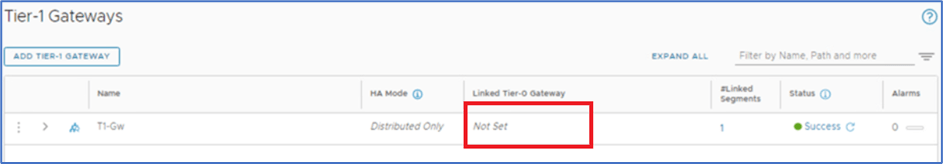
Figure 10 : Tier-1 Gateway
Select Tier-0 gateway (Created in previous steps ) and click on save. Scroll down and click on Close Editing.

Figure 11 : Attach Tier-1 gateway to Tier-0
Pre-Validation before enabling OSPF configuration
We will capture NSX-T configuration and connectivity between Web server(172.16.10.11) and Admin PC(172.20.10.80) via ping.
Admin PC
IP configuration and ping test towards Web server
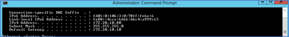
Figure 12: Admin PC IP configuration
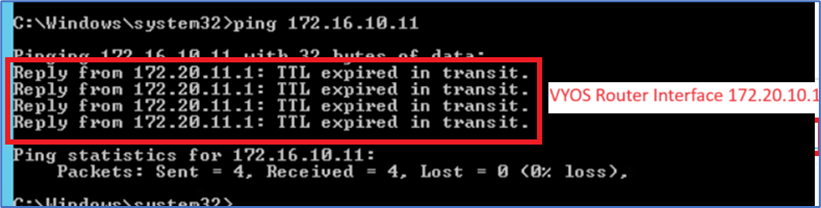
Figure 13 : Ping from Admin PC to Web server
WEB Server
IP address and ping validation towards Admin PC

Figure 14 : Web server IP and ping output
Validation on NSX-T
Routes on NSX-T Edge Gateway
SSH to both NSX-T edge gateway and login to Tier-0 SR VRF to validate routes. Verify that route for Admin PC subnet (172.20.10.0/24) or default route is not present towards Physical router VLAN 200 Gateway IP 192.168.200.1

Figure 15 : Edge Node 1 Routing table
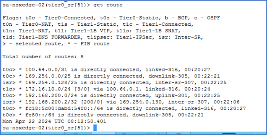
Figure 16 : Edge Node 2 Routing Table
Routes on Physical (Underlay) Router
SSH to Physical router and validate that route towards Overlay Segment (172.16.0.0/16) is not available.
Note : In your scenario, Underlay router can be different like CSR 1K .
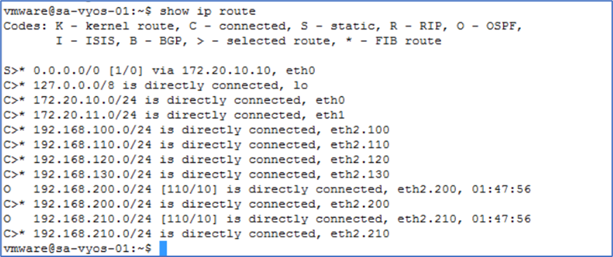
Figure 17 : Physical Router Routing Table
Configuration
To apply OSPF configuration at Tier-0 router, Follow below steps.
Login to NSX-T Manager >> Networking >> Tier-0 Gateway >> Click on 3 vertical point and select edit.
Scroll down and disable BGP configuration as BGP is enabled on default Tier-0 configuration. Turn OFF all BGP related configuration.

Figure 18 : Turn OFF BGP configuration
Click on save and validate that BGP configuration has been disabled.
Now scroll down and Expand OSPF (Which will be showing as disabled). Click on enabled and set to apply OSPF AREA configuration.

Figure 19 : OSPF Configuration
New Window will pop-up . Click on Add Area Definition and apply below configuration
Area ID: 0
Type: Normal ( OSPF Support OSPF area Normal and NSSA only )
Click on save to complete configuration

Figure 20 : OSPF Area Configuration
Validate that OSPF Area configuration has been configured successfully and click on Close.

Figure 21 : OSPF Area Validation
Next Step is to Enable OSPF interfaces at NSX-T Tier-0 Gateway.
Click on SET option in OSPF configured interfaces.

Figure 22: OSPF Interface Configuration
New Window will popup and click on CONFIGURE INTERFACE.
Select both EDGE uplink interfaces, Area ID (0), Network Type (Broadcast). You can also apply other configurations like BFD, OSPF timers as per your design.
Note: NSX-T supports only OSPF Area Broadcast and P2P.

Figure 23: OSPF Interface Configuration
Validate that both EDGE uplink interfaces have been configured for OSPF.

Figure 24 : OSPF Validation
Click on Save to complete Tier-0 configuration.

Figure 25 : Click on save
In next step we will enable Route-redistribution for OSPF
By default, Route Re-distribution is enable for BGP. We will disable BGP protocol and enable re-distribution for OSPF.
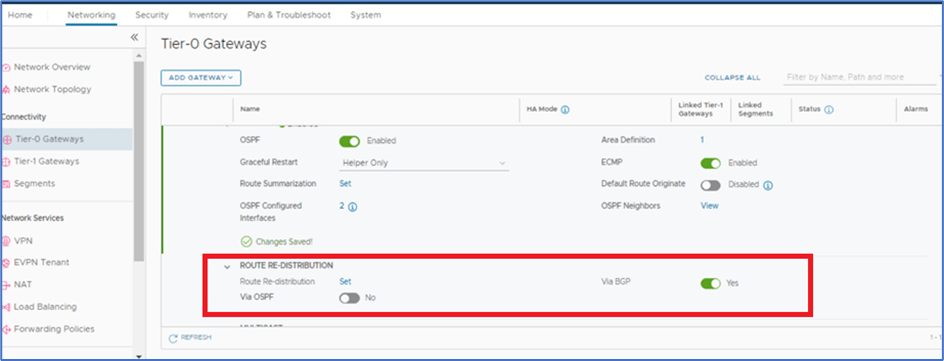
Figure 26 : OSPF re-distribution
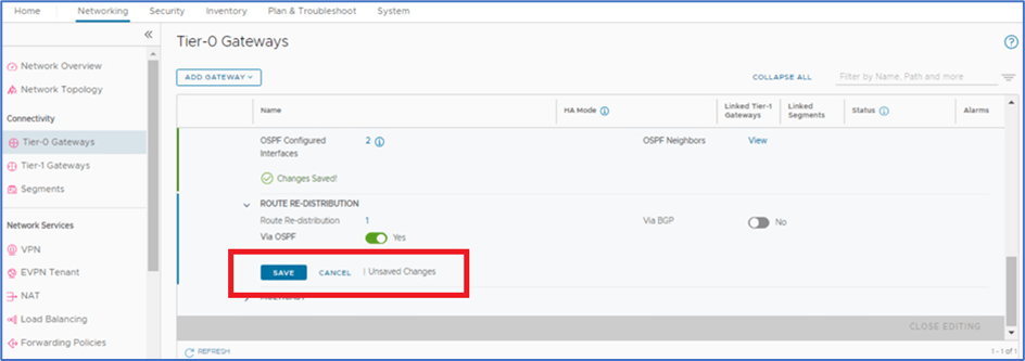
Toggle OFF BGP and enable OSPF

Figure 27 : OSPF Re-distribution configuration
Click on SET to configure Re-distribution. Here we will enable routes which needs to be advertised towards physical router from NSX-T.

Figure 28 : Click on Set
Click on ADD ROUTE RE-DISTRIBUTION. Provide below information and click on SET.
Name:
Destination protocol : OSPF

Figure 29 : OSPF Re-Distribution Configuration
Select Tier-0 and Tier-1 Subnets which needs to be advertised in OSPF and click on APPLY to save configuration.

Click on Add to apply configuration.
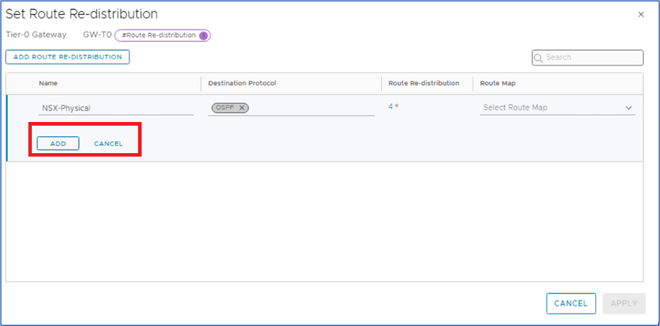
Figure 30 : Click on Add to apply configuration
Click on APPLY

Click on save to apply configuration
Click on Close Editing

Apply configuration on Physical router
We have applied below configuration on Physical router
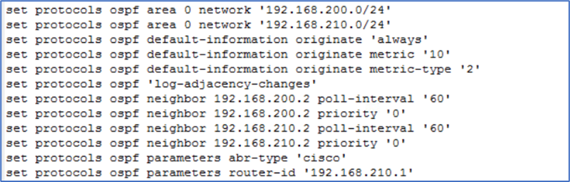
Figure 31 : Physical Router configuration
Validate that OSPF is enabled on Physical router

Figure 32 : OSPF Configuration validation
Validation
VM Connectivity
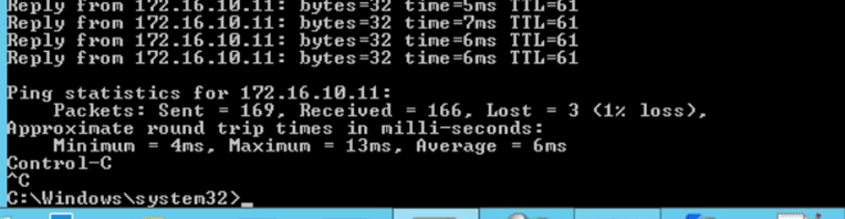
Login to Web server and ping ADMIN PC (172.20.10.80) . Now connectivity is in place and Ping reply must be from Admin PC .
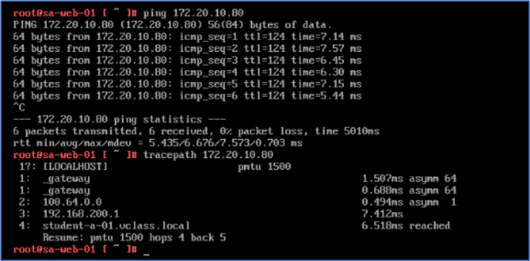
Figure 33 : Ping & Traceroute from Web server
ADMIN PC

Figure 34 : Ping & Traceroute from Admin PC
Routes on EDGE gateways
Validate that we are getting default route on NSX-T edge gateways from OSPF.
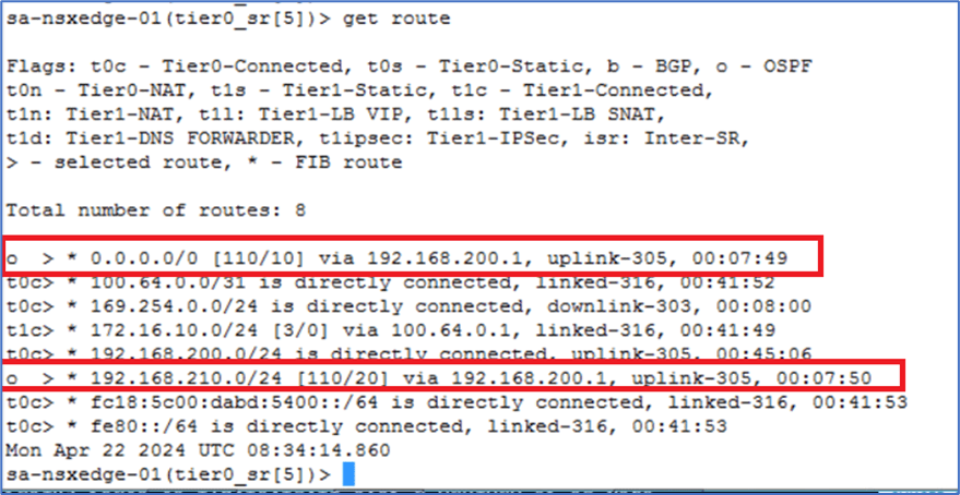
Figure 35 : Routing Table on Edge Node A

Figure 36 : Routing Table on Edge Node B
Validate OSPF database in NSX-T edge gateways

Figure 37 : OSPF database in Edge Node A

Figure 38 : OSPF database in Edge Node B
Validate OSPF database in Physical router
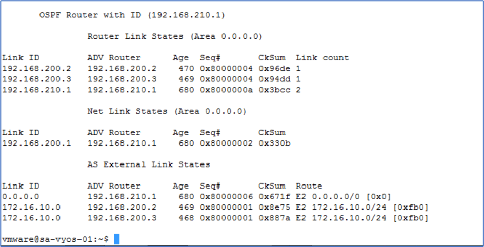
Figure 39 : OSPF database in Physical router
Routes on Physical Router
Validate that Physical router is getting NSX-T Overlay networks as external network E2.

Figure 40 : Routing on Physical router
Edge Failover Testing
We will test failover scenario when one Active edge node fails. To simulate, We are going to power Off Active Edge Node A and will ping Admin PC from Web server to monitor traffic failover.
Login to Vcenter server, and power off Sa-nsxEdge-01 VM to simulate Edge Node failure.

Figure 41 : Power OFF Edge Node A
Once you click on Power Off , system will prompt you to confirm. Click on Yes and validate that VM is powered off.
Validate NSX-T Edge status
Login to NSX Manager >> Networking >> Tier-0 Gateway >> Click on Active Active to identify status. Sa-nsxEdge-01 edge node will be reflecting as Unknown.

Figure 42 : Edge Node Status
Validate routes on Physical router
Now only 1 route is in routing table at Physical Router
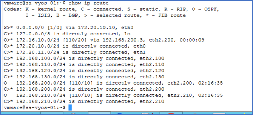
Figure 43 : Physical Router Routing Table
Validate ping test
We will perform ping test from Admin PC (172.20.10.80) and web server (172.16.10.11) .
We have observed that 3 packets were lost while traffic failover during edge cutover.
Conclusion
In this blog, we covered NSX Tier-0 Deployment in Active Active mode and enable OSPF route.


Leave a comment