Introduction
In this Blog, we will cover Static Routing configuration instead of dynamic routing to connect with Physical infrastructure. NSX-T Support both static and dynamic routing where BGP & OSPF can be leveraged as dynamic routing protocols and static route is leveraged for static.
Topology Overview
Refer below topology diagram to get high level overview of infrastructure.
We have Admin PC (172.20.0.80) which is connected to VYOS Router. NSX-T Datacenter have Tier-0 router deployed in Active/standby mode. Web servers is connected to WEB segment (overlay) with subnet 172.16.10.0/24 and attached with Tier-1 gateway.
NSX-T datacenter and Physical Infrastructure ( VYOS Router) is connected with VLAN 100 and we will configure static route to allow connectivity between Admin PC (172.20.0.80) and Web server (172.16.10.10)
After Static routing in place, Traffic flow from Web server to Admin PC will follow below path
Web Server >> Tier-1 (Segment gateway) >> Tier-0 Gateway >> VYOS router >> Admin PC

Figure 1: Topology Overview
Note : In this Topology, below objects are already placed.
- NSX-T Manager
- Transport Nodes (ESXI) are prepared for NSX-T
- NSX-T edge cluster with two Nodes are deployed.
- Tier-0 and Tier-1 routers are deployed.
- Overlay segment (Web) is deployed
Pre-Validation
We will capture NSX-T configuration and connectivity between Web server and admin VM via ping.
NSX-T Configuration
Please refer below screenshots for NSX-T configuration like Segments, Teir Gateway, etc. All those components are already configured.

Figure 2: NSX-T Segments
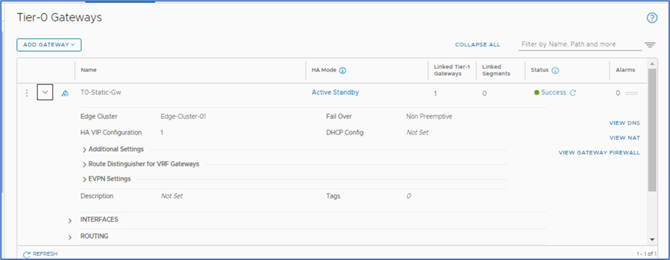
Figure 3 : Tier-0 Gateway

Figure 4 : Tier-1 Gateway
VM connectivity
We tried to ping Admin PC from Web server and VLAN gateway hosted on VYOS router . Currently Connectivity is not in place so we are getting Destination Host Unreachable.
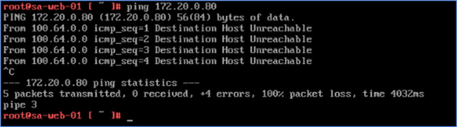
Figure 5 : Ping from Web server to Admin VM

Figure 6: Ping from Web server to VLAN gateway
Note : 100.64.0.0 belongs to Auto plumb subnet which get created while attaching Tier
Configuration
To apply static configuration and HA VIP configuration, Follow below steps.
Step 1 : Login to NSX-T Manager and click on Networking >> Tier-0 gateway >> click on 3 vertical dots and click on Edit >> Click on HA VIP configuration.

Figure 7 : Click on HA VIP Configuration
Step 2: Click on ADD HA VIP configuration and add VIP IP address and select Edge Uplink for which , HA VIP needs to be applied.
In our example, VLAN is 100 and we have 2 Edge nodes interface.
Click Add to apply changes.

Figure 8 : Apply VIP configuration
Step 3 : Click on Save Tab to apply configuration at Teir-0 router level.
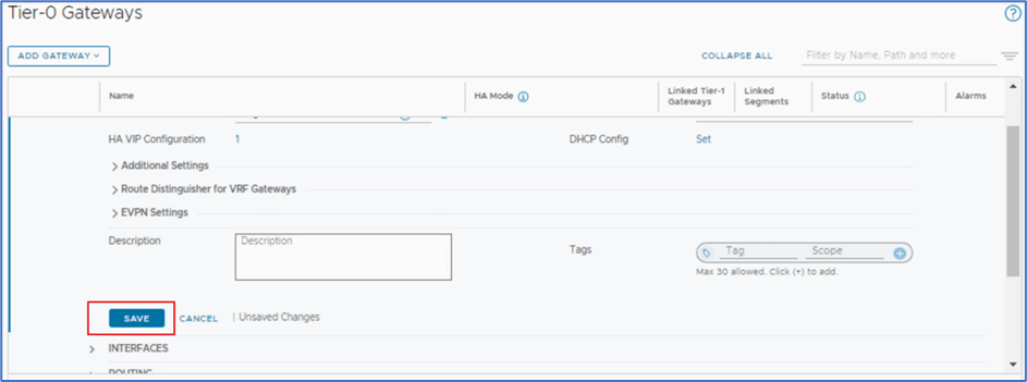
Figure 9 : Click on save
Note : Ha VIP IP gets configured on Active Edge interface only. In this Topology, Edge Node A is Active . We will SSH both Edge nodes and validates VIP configuration.
Login to Active Edge Node

Figure 10 : Active Edge Node Configuration
Login to Standby Edge Node

Figure 11 : Standby Edge Node Configuration
Step 4 : Apply Static route on Tier-0 router to apply North end routing.
Expand Routing section on Tier-0 router and click on Static route >> Set.
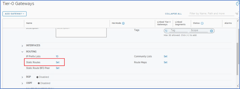
Figure 12 : Click on Set option to apply static route
Click on Add Static Route and provide below information to apply static route. In this Topology, we will apply Default route towards Physical router.
Name: Default route
Network: 0.0.0.0/0
Next Hop : 192.168.100.1 ( VLAN SVI )

Figure 13 : Provide routing information
Click on Set and apply provide next HOP information as per below screenshot
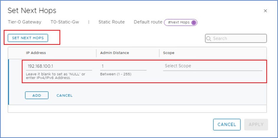
Figure 14 : Apply Next Hop IP
Click on ADD and then Apply changes .
Step 5 : Apply Routing on Physical Router ( Southend Routing) .
Login to VYOS router and apply Static routes for Overlay Network towards HA VIP IP on NSX-T Tier-router .
Note : You might have another underlay router like Cisco CSR . Please validate vendor configuration before applying changes.
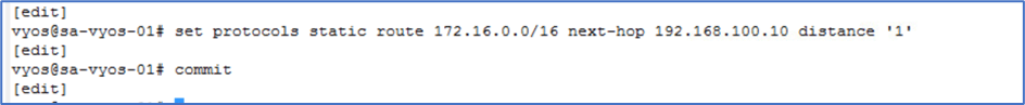
Figure 15 : Static Route on VYOS Router.
We have applied static routing on both NSX-T Tier-0 and VYOS router. Now we have to validate connectivity between WEB server (Overlay network ) and Admin PC ( Underlay Network)
Validation
Ping Test from Web server (172.16.10.11) PC to Admin PC(172.20.0.80) , Underlay Network ( 172.20.10.1) and Web server gateway ( 172.20.0.1).

Figure 16 : Ping Test from Web server
Traceroute from Web VM towards Admin PC.

Figure 17 : Traceroute from Web VM
Ping and traceroute from Admin PC towards Web Server VM.

Figure 18 : Web Server response from Admin PC
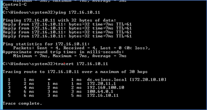
Figure 19 : Traceroute from Admin server to Web server.
Edge Failover
Now , We will test failover scenario when Active edge node fails. To simulate , We are going to power Off Active Edge Node and will ping Admin PC from Web server to monitor failover .
To identify current Active Edge , Login to NSX Manager >> Networking >> Tier-0 Gateway >> Click on Active Standby.
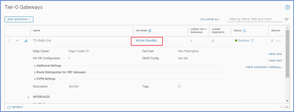
Figure 20 : Click on Active-Standby to get Node details
In our scenario, Sa-nsxEdge-01 is Active. We will perform Power off activity for this node.

Figure 21 : Active Edge Node
Ping Test
Login to Web server ( Console/SSH) and initiate ping towards Admin PC (172.20.0.80).

Figure 22 : Ping from Web server to Admin PC before Failover
Login to Vcenter server, and power off Sa-nsxEdge-01 VM to simulate Edge Node failure.
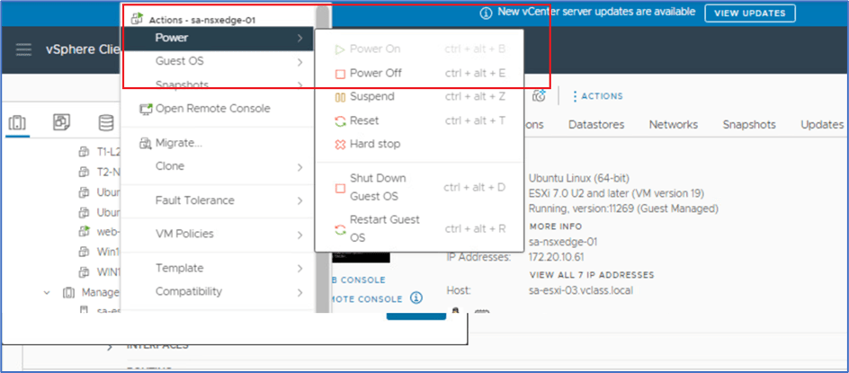
Figure 23: Power Off Edge Node VM
Once you click on Power Off , system will prompt you to confirm. Click on Yes and validate that VM is powered off.
Validate Failover
Login to NSX Manager >> Networking >> Tier-0 Gateway >> Click on Active Standby to identify status. Sa-nsxEdge-01 edge node will be reflecting as Unknown.

Figure 24 : Edge status after Failover
During this activity, we observed 3 ping failure from web-server to Admin PC.

Figure 25 : Ping output after failover
HA-VIP IP Validation
Currently Edge Node 02 is Active and HA VIP has been migrated from Edge Node 01 to 02. SSH to Edge Node 02 and validate configuration.

Conclusion
In this blog , We covered NSX Tier-0 Deployment in Active standby mode and enable Static route with HA VIP configuration. In later blogs, We will test scenario with Active-Active Mode and static route .


Leave a comment